St-Link V2 Simulator Download Programmer Original Stm32F103C8T6 Arm Stm32 Minimum System Development Board Stm32F401 Stm32F411
- 140 reviews
- 4325 Sold
Extra Discount:
| Items | 2+ | 5+ | 10+ | 50+ |
|---|---|---|---|---|
| Discount | 10% | 15% | 20% | 30% |
| Unit Price | $1.53 | $1.44 | $1.36 | $1.19 |
Customer Reviews
*Note: Some reviews have been processed by Google Translate!Condition: New
Type: Voltage Regulator
Model Number: ST-Link V2 / STM32F103C8T6
Supply Voltage: STLINK V2
Dissipation Power: STM32F103C8T6 / STM32F103C6T6
is_customized: Yes
Operating Temperature: STM32F401 STM32F411 STM32F4
Application: Computer
Package: SMD
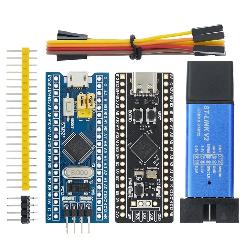
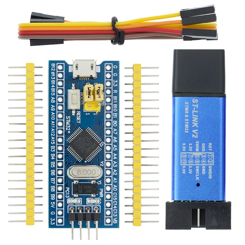
ST-Link V2 Mini STM8 Simulator Download
Specifications
lInput voltage (USB):5V
lOutput Voltages: 3.3V, 5V
lInterfaces:SWIM, SWD
lConnectors:USB, 10 pin (molex type)
lDimensions:57mm x 20mm x 8mm[2.2in x 0.7in x 0.3in]
The St Link V2 programmer supports STM8 and STM32 microcontrollers
The module supports automatic firmware upgrades to ensure the maintenance of ST products. The factory firmware has been updated to the latest version V2.J17.S4.
2x5 headers 2.54 mm (0.1 in) apart, including cables (4 f-f jumper wires)
USB 2.0 full speed compatible interface
lWARNING: STM32 chips run on 3.3V, most breakout boards will include a voltage regulator so it can be powered from USB, and STLink dongles will provide a3.3V VCC pin to power up the chip.
lDo not connect the board to the PC using USB while the chip is powered up usingthe ST-Link V2 programmer!
lConnect one or another but not both simultaneously. The ST-Link V2 dongle provides a 5V pin as well. It is not going to be used because the STM32 chips are not5V tolerant, the 3.3V pin has to be used only.
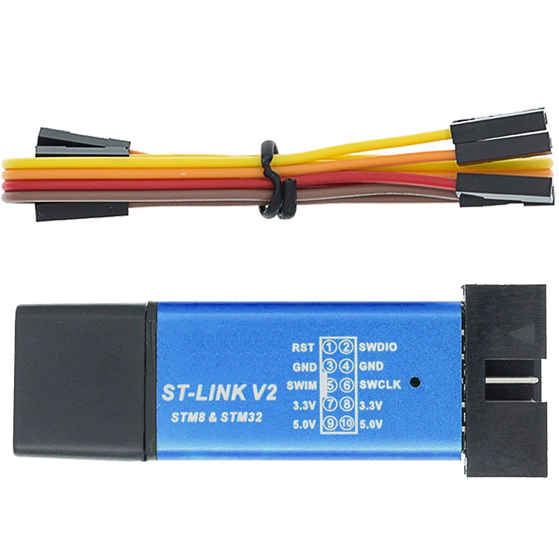
Pinout

STM32F103C8T6 ARM STM32 Minimum System Development Board Module For Arduino
This is a core chip based on for CS32F103C8T6 ARM core board, features are as follows:
1, the board based on the most basic MCU circuit, 8M and 32768 crystal circuit, USB power supply circuit.
2, the core board is divided into two rows leads to all the I / O port.
3, with SWD simulation debug download interface, simple and convenient, debugging speed.
4, the use of the Mirco USB interface, you can do USB communication and power supply, USB interface, compatible with the ordinary Andrews mobile phone charger interface.
6, RTC crystal Epson brand, easy to start, more stable.
7, with double pin, but the pin does not default welding, the user according to their own application scenarios to choose their own welding direction. If welding is required, please tell the owner.
Keil can be used to compile, IAR compiler, can be downloaded through the J-Link or USART1 procedures, the procedures are the owner and debugging procedures, there are problems can consult the owner.
Chip Description:
1, 32F103C8T6
Package Type: LQFP;
Number of pins: 48;
Kernel: Cortex-M3;
Operating frequency: 72MHz;
Storage resources: 64K Byte Flash, 20KByte SRAM;
Interface Resources: 2x SPI, 3x USART, 2x I2C, 1x CAN, 37x I / O ports,
Analog-to-digital conversion: 2x ADC (12-bit / 16-channel)
Timers: 3 general timers and 1 advanced timer
Debug Download: Support JTAG / SWD debug interface to download, support for IAP.
2, RT9193: 3.3V regulator chip, the maximum output of 300mA.
Interface description:
1, SWD interface: support for simulation, download and debug.
2, Mirco USB interface: power supply and USB communication, does not support the download.
3, USART1 interface: USART1 can be used to download the program, or use the USART1 for communication.
4, MCU pin interface: leads all I / O port pins, easy to connect with peripherals.
5, 5V and 3.3V power input and output interface: commonly used in external power supply, or with other modules for common ground treatment
Other Device Description:
1, Power LED (PWR): Power indicator status, can determine whether the power supply is stable.
2, the user LED (PC13): to facilitate the I / O output test or indicate the program running.
3, start jumping choose programming mode: (1, the user flash memory 2, SRAM 3, system memory).
4, reset button: reset chip for the user program.
5, 8M Crystal: The frequency can be set to make the system clocked at 72MHz.
6,32.768KHz Crystal: Available for built-in RTC, or for calibration.
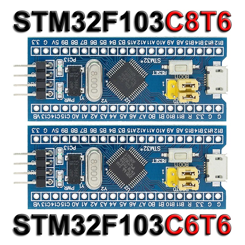
STM32F103C8T6 VS STM32F103C6T6
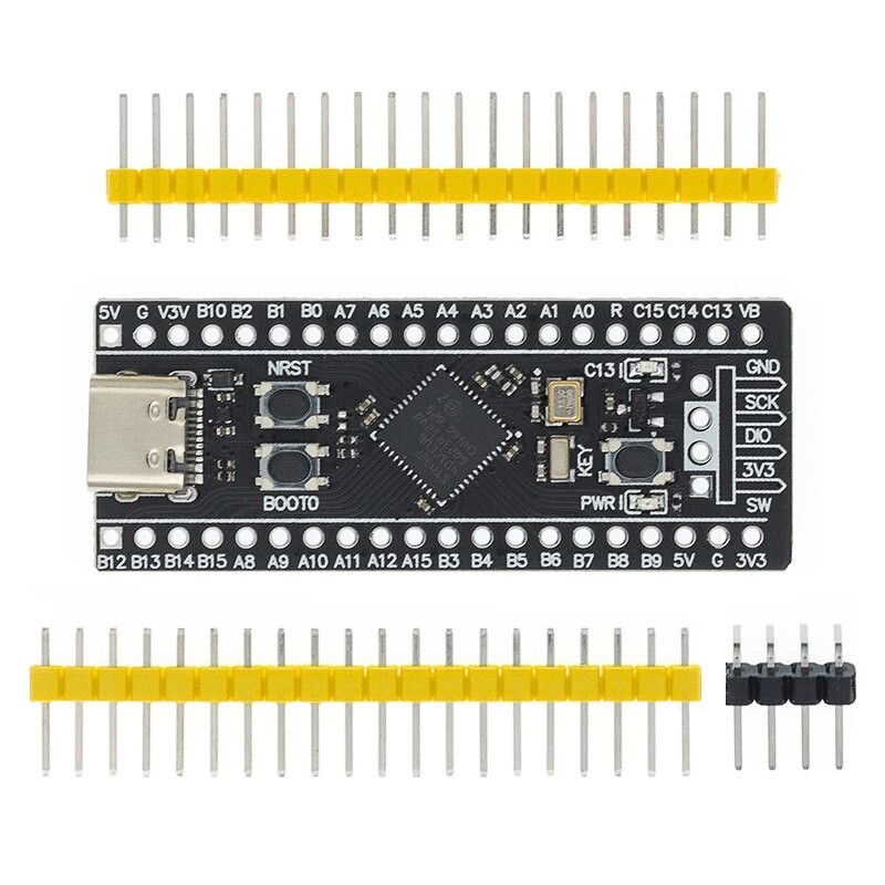
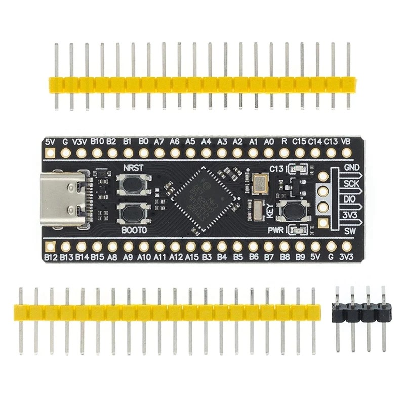
STM32F401CCU6 3.0/STM32F411CEU6 3.0 Development Board
STM32F401CCU6 core board V3.0Freq. 84Mhz ROM:256KB RAM:64KB STM32F411CEU6 core board V3.0Freq. 100MHZ ROM:512KB RAM:128KB
Support MicroPython programming, provide available MicroPython firmware, see the link for configuration files, but do not provide technical answers!Support Arduino programming, see Github https://github.com/stm32duino/Arduino_Core_STM32 for detailsBoards with version V1.3 and above have 3 buttons, reset button, BOOT0 button, and user buttons.How to enter ISP mode Method 1: Press and hold the BOOT0 button and the reset button under the power-on state, then release the reset button, and release the BOOT0 button after 0.5 seconds Method 2: Hold down the BOOT0 key when power is off, and release the BOOT0 key 0.5S after power on DFU mode: just use the data cable to connect to the computer, if there is a problem of unrecognized, you can properly heat the chip (25 ° C), and then re-enter the ISP mode Serial port mode: use USB to serial port to connect PA9 and PA10 of the core board No need for USB to serial port, no debugger, no computer driver, just a TYPE-C data cable to complete the firmware downloadPress and hold the KEY button, click the reset button, LED C13 flashes, release the KEY button to enter
STM32F411CEU6 core board 128KB RAM 512KB ROM
1. 25MHZ high speed crystal oscillator & 32.768Khz 6PF low speed crystal oscillator
2. Flash pads are reserved, providing USBDisk&&FATFFS routines
3. Jumper cap can be used directly without installation.BOOT0 internal 10K resistance pull-down
4. Factory has burned breathing lamp &&USBCDC test procedures.
5. Provide available MicroPython firmware, configuration files
6. Adjust the direction of the jumping cap if it cannot be installed.Because the jump cap is wide on one side and narrow on the other.
7. V1.3 board with 3 buttons: reset key, BOOT0 key and user button.
V1.3 serial download and DFU download: connect to PA9 and PA10 (connect to usb in DFU mode) by pressing BOOT0 key and reset key, and then release the reset key. After 0.5 seconds, release the BOOT0 key to enter serial download or DFU download. The corresponding software is flymcu or CubeProg.
Jump cap version download: BOOT0 connect to high, BOOT1 connect to high, enter the serial port to download or DFU download, the software is the same as above.