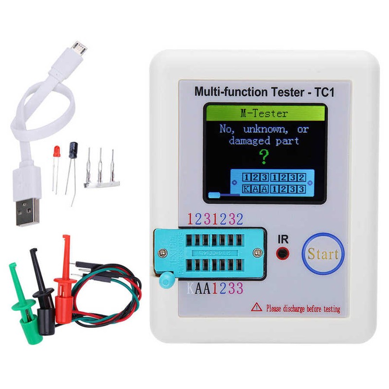
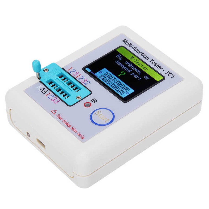
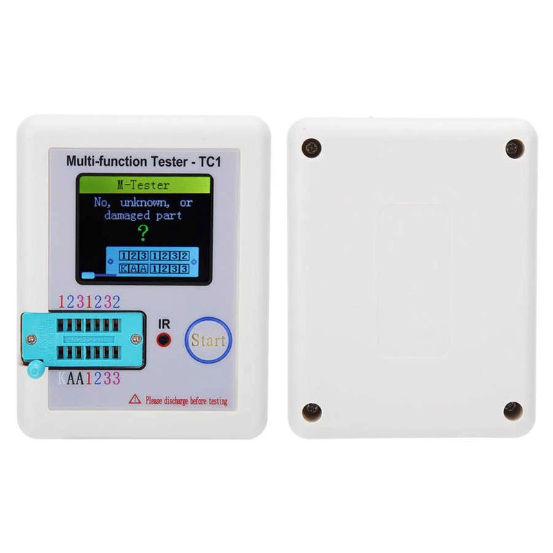
Lcr-Tc1 Transistor Tester Multimeter Tft Lcd Display Diode Triode Capacitance Resistor Meter Npn Pnp Mosfet Multimeter
- 140 reviews
- 179 Sold
Customer Reviews
*Note: Some reviews have been processed by Google Translate!Model Number: LCR-TC1
is_customized: Yes
Certification: NONE
Feature 1: Transistor Tester
Feature 2: Multifunction Transistor Tester
Feature 3: Display Screen Transistor Tester
Feature 4: Diode Transistor Tester
Feature 5: Capacitance Meter

Feature:
1. Widely used to detect NPN and PNP transistor, capacitors, resistors, diodes, transistors, N‑channels and triangles and batteries.
2. Can be used to detect infrared waving form, Zener diode can be detected, with self‑calibration function.
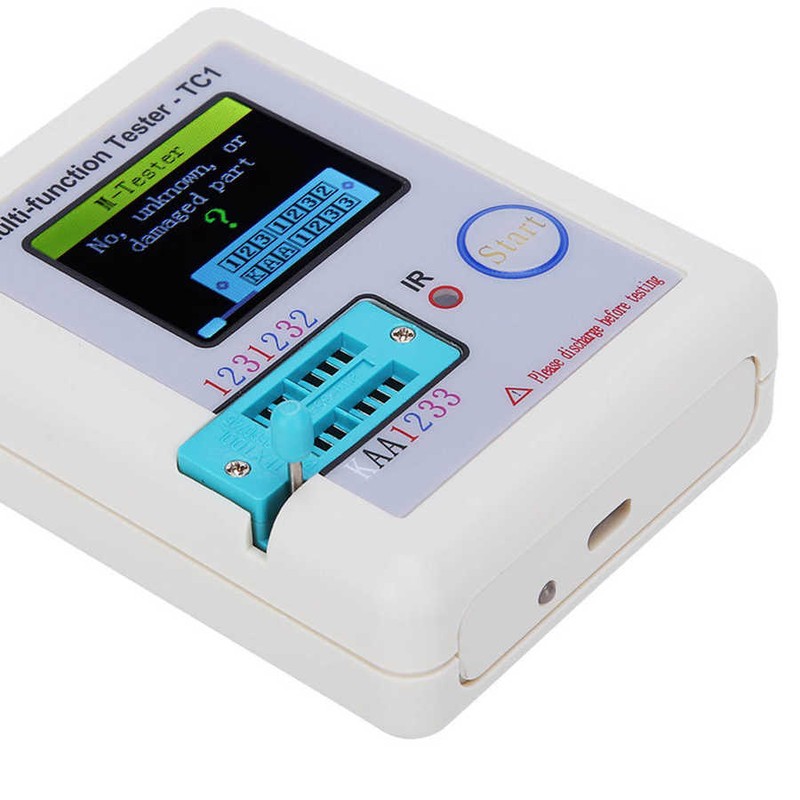
3. Adopt 1.8in TFT screen, full‑color screen graphic display, more convenient reading.
4. With 4000mAh rechargeable battery, long battery life, easy to use.
5. Using high quality materials, strong and durable, has a long service life
Specification:
Item Type: Transistor Tester
Product Material: ABS
Features: Used to detect NPN and PNP transistors, capacitors, resistors, diodes, triodes, N-channel and P-channel MOSFETs, IGBTs, JFETs, triodes and batteries. It can also be used to detect infrared waving forms.
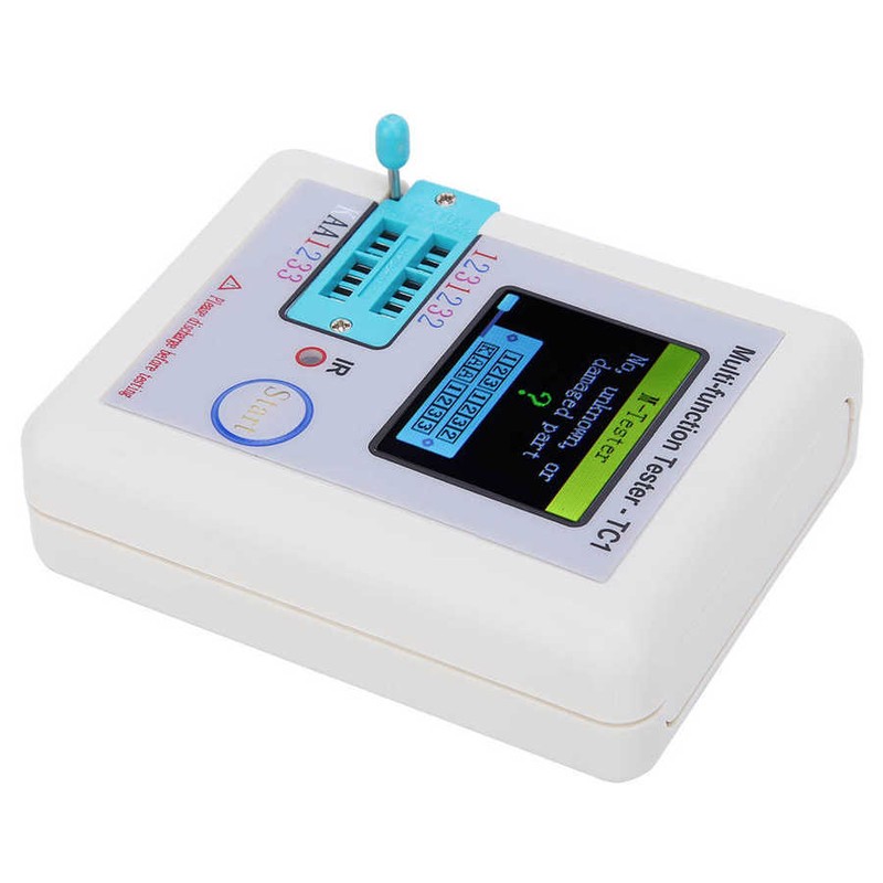
Display: 1.8in TFT screen
Diode Range: 4.5V
Zener Diode: Transistor Detection Area: 0.01-4.5V
Zener Diode Detection Area: 0.01-30V
Capacitance: 25pF-100mF
Resistance: 0.01-50MΩ
Inductance: 0.01mH-20H
Battery: 0.1-4.5V 4000mAh
Power Mode: Rechargeable Lithium Battery
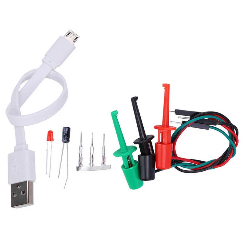
Package List:
1 x Transistor Tester
3 x Probe
1 x Accessory Package (Data Cable + 3 Accessories)


Description:


②Square wave and PWM outputinterface
③voltage measurement interface
④Original test bit
⑤In the original test base
⑥160×128 full color display
⑦Frequency messurement interface
⑧Power adapter socket
⑨9V battery contact 9V
⑩Work indicator
Features | English | Russian |
Switch off | Yes | |
Transistor | Yes | |
f-Generator | Yes | |
10-bit PWM | Yes | |
| Yes | |
C+ESR@TP1:3 | Yes | |
1-||-3 | Yes | |
DS18B20 | Yes | No |
C(uF)-correction | Yes | |
IR_Decoder | Yes | No |
IR_Encoder | Yes | No |
DHT11 | Yes | No |
SelfTest | Yes | |
Voltage | Yes | |
FrontColor | Yes | No |
BackColor | Yes | No |
Showdata | Yes | |
 :3
:3

Scratchpad BYTE
TEMPERATURE LSB | 0 |
TEMPERATURE MSB | 1 |
TH/USER BYTE 1 | 2 |
TL/USER BYTE 2 | 3 |
CONFIG | 4 |
RESERVED | 5 |
RESERVED | 6 |
RESERVED | 7 |
CRC | 8 |
For example, the value read once is Scratchpad: EC014B467FFF0C102A has the following relationship:
Scratchpad Value BYTE
TEMPERATURE LSB | EC | 0 |
TEMPERATURE MSB | 01 | 1 |
TH/USER BYTE 1 | 4B | 2 |
TL/USER BYTE 2 | 46 | 3 |
CONFIG | 7F | 4 |
RESERVED | FF | 5 |
RESERVED | 0C | 6 |
RESERVED | 10 | 7 |
CRC | 2A | 8 |
64-bit ROM: The globally unique device ID of each DS18B20 read by the tester. The ID has a length of 64 bits. Divided into 3 parts.

8-BIT FAMILY CODE | 28 |
48-BIT SERIAL NUMBER | 041636584DFF |
8-BIT CRC CODE | A1 |


