Df-96Ed Controllore Di Livello Acqua Automatico Interruttore 10A 220V Serbatoio Di Acqua Sensore Di Rilevamento Del Livello Del Liquido Regolatore Della Pompa Dell'Acqua 2 M Fili
- 139 recensioni
- 1018 Venduto
USD $7.46IVA Inclusa
Solo per drop shipping e all'ingrosso
Come pagare?
- Spedito in 24 ore tramite spedizione veloce.
- Consegna stimata da 5 a 9 giorni lavorativi.
Recensioni dei clienti
*Nota: alcune recensioni sono state elaborate da Google Translate!Forniture fai -da -te: impianto idraulico
Numero modello: DF-96D
Certificazione: nessuna
Peso del pacchetto: 0,3 kg (0,66 libbre)
Dimensione del pacchetto: 10 cm x 8 cm x 8 cm (3.94in x 3.15in x 3.15in)
63060
Water Level Controller Switch
| Specifica | |
| Tipo: | DF-96DAggiornatoVersione |
| Di lavoroTensione: | AC220 V/50 HZ |
| MaxCorrente: | 10A (UsoIl30ADi ritardo) |
| Installazione: | DinFerroviarioMontaggio |
| Di alimentazioneIl consumo di energia | ≤2W |
| Di trasmissioneSegnale: | 500 M |
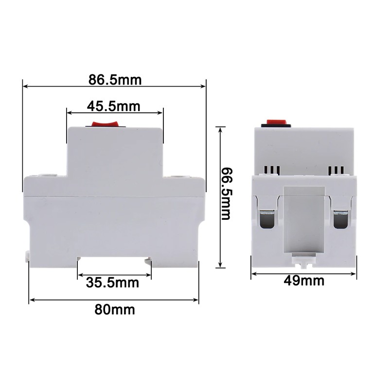
| Formato: | 126*88*51 millimetri |
Cornici e articoli da esposizione includono:
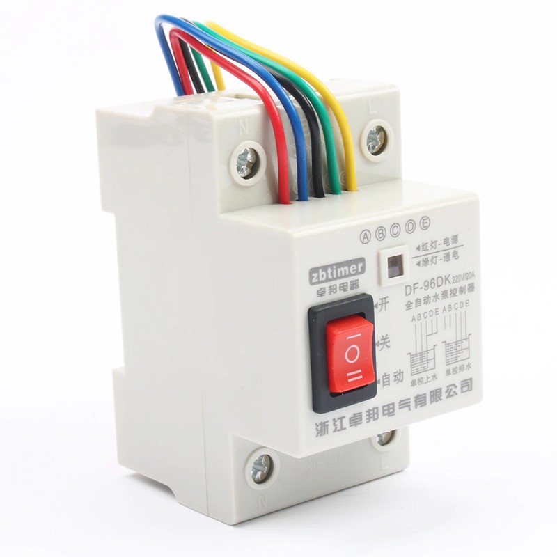
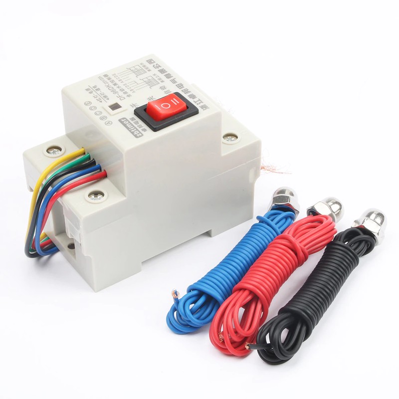
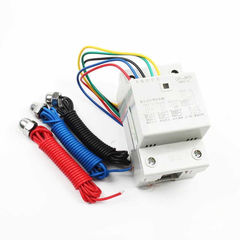
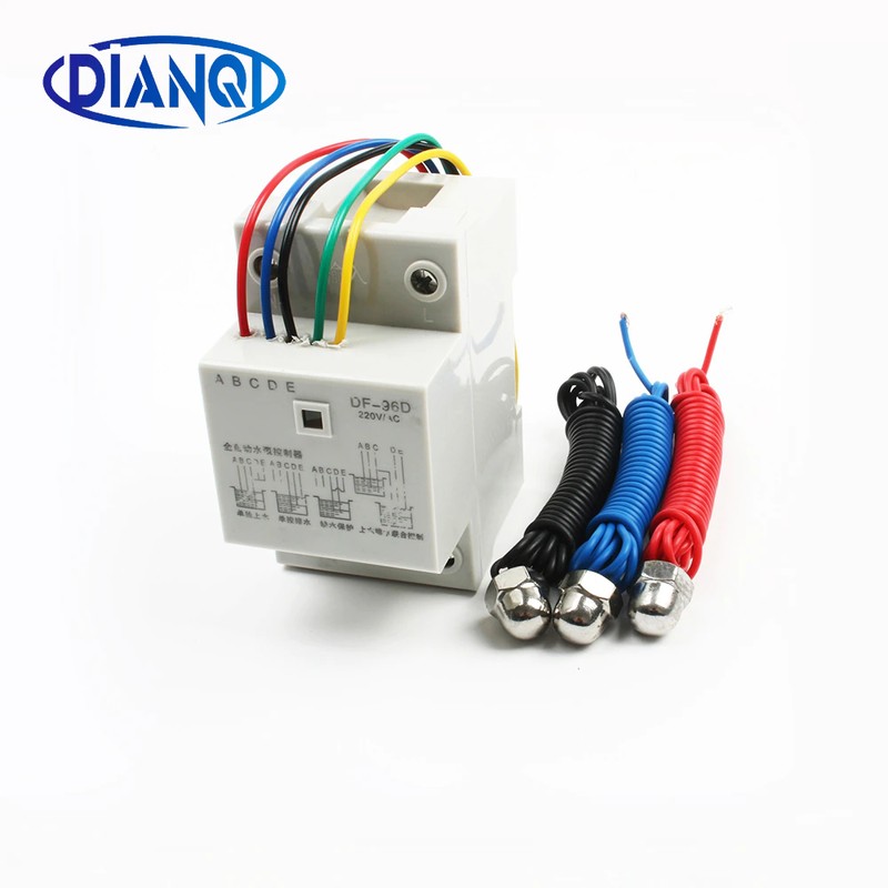
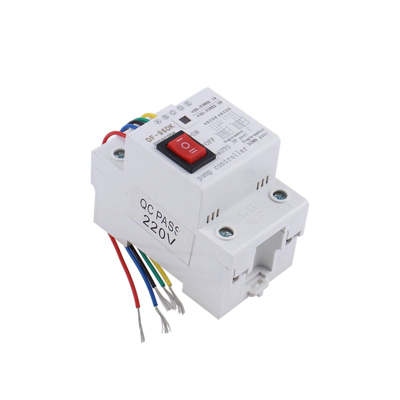
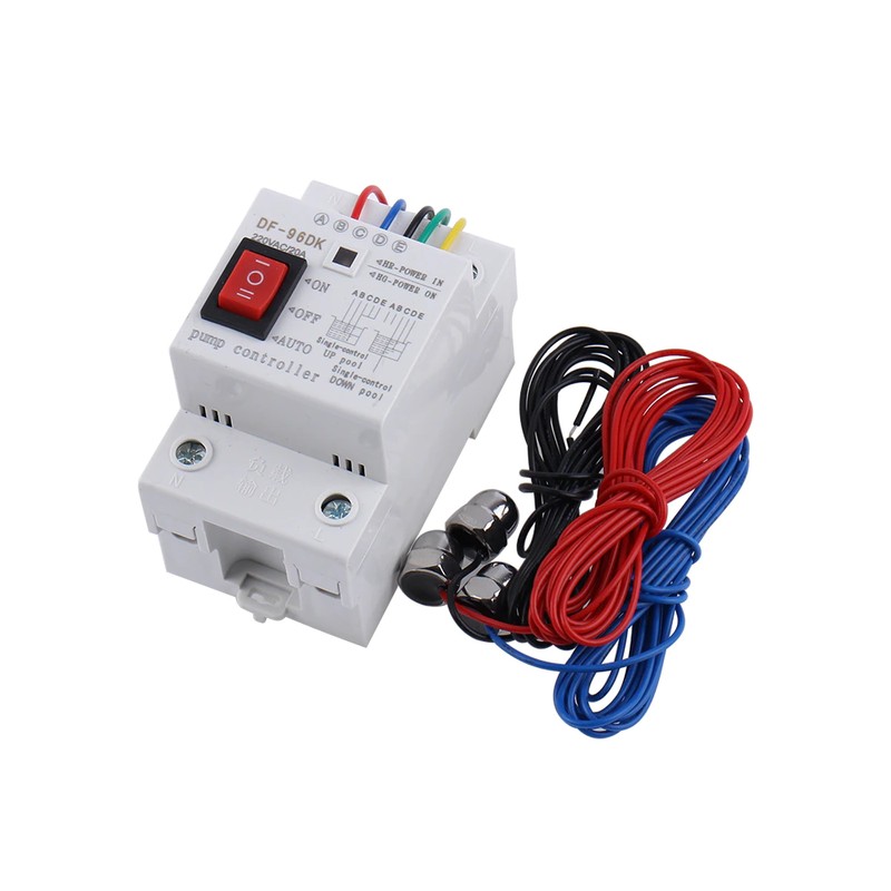
1 pcsControllo automatico del Livello Dell'acqua Interruttore
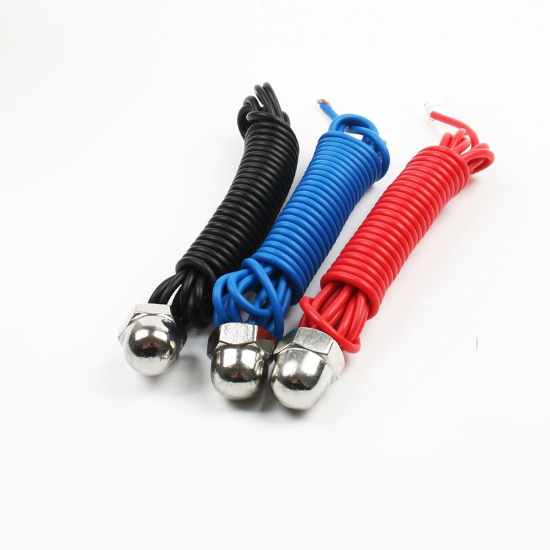
3 pcs 200 CENTIMETRI Sensore
Singolo-control UP piscina (acqua di stoccaggio) le istruzioni di installazione mostrato in figura 1
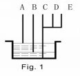
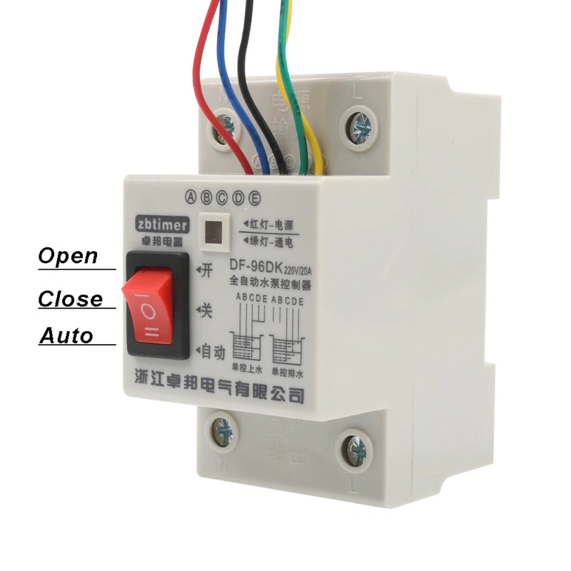
A (rosso)-Superiore di acqua punto di controllo di livello. Quando il livello dell'acqua arriva a UN punto,
La sonda toccare l'acqua e il controller può fermare la pompa automatica.
B (blu)-Più Basso punto di controllo di livello dell'acqua. Quando il livello dell'acqua scende punto B,
La sonda fuori di raggiungere l'acqua e il controller può avviare la pompa automatica.
C (nero)-Deve essere posto in fondo della piscina come la linea comune.
D (verde) e E (giallo) sono collegati con C (nero).
Singolo-control GIÙ piscina (acqua di scarico) le istruzioni di installazione mostrato in figura 2.
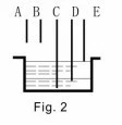
E-Superiore di acqua punto di controllo di livello. Quando il livello dell'acqua arriva a E punto,
La sonda toccare l'acqua e il controller può avviare la pompa automatica.
D-Più Basso punto di controllo di livello dell'acqua. Come di livello del liquido scende punto D,
La sonda fuori di raggiungere l'acqua e il controller può fermare la pompa automatica.
C-Deve essere posto in fondo della piscina come la linea comune.
A & B-scollegato
1. La mancanza di acqua le istruzioni di installazione di protezione mostrato in figura 3.
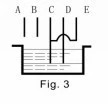
C & D-Più Basso livello dell'acqua punti di controllo. Quando il livello dell'acqua scende questo punto,
C o D sonda fuori di raggiungere l'acqua e il controller può fermare la pompa automatica.
E & C-short-collegato;
A & B-scollegato
2. Controllo congiunto SU e GIÙ piscina istruzioni di installazione mostrato in figura 4.
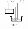
A-Superiore di acqua punto di controllo di livello in UP piscina. Quando il livello dell'acqua arriva a UN punto, la sonda toccare l'acqua e il controller può fermare la pompa automatica.
B-Più Basso punto di controllo di livello in UP piscina di acqua. Quando il livello dell'acqua scende UN punto, la sonda fuori di raggiungere l'acqua e il controller può avviare la pompa automatica.
C-Deve essere posto in fondo di SU e GIÙ per piscine come la linea comune.
D-Più Basso punto di controllo di livello in GIÙ piscina di acqua. Quando il livello dell'acqua scende punto D, la sonda fuori portata e il controller può fermare la pompa automatica.
E-Superiore punto di controllo di livello in GIÙ piscina di acqua. Quando il livello dell'acqua arriva a E punto, la sonda raggiungere l'acqua e il controller può avviare la pompa automatica. Poi piscina inizia a scarico di acqua. Se non, E punto scollegato
Utilizzato per risolvere il problema:
1. sul potere, ma nessun lavoro di:
Un. Controllare la spia rossa è accesa o non. Se non, fare il collegamento è abbastanza buono;
2. quando il livello dell'acqua è al di sopra o al di sotto di sonde ma la pompa non avviare o arrestare da auto, si prega di controllare come il seguente.
Un. se la sonda è posto troppo alta o bassa in modo che il livello dell'acqua può raggiungere o fuori di raggiungere;
B. La linea di collegamento di superiore e inferiore o sonda è dislocazione per errore o breve collegata;
C. To controllare la sonda che si tratti di ruggine o non o la connessione è abbastanza buono.
D. C-Controllare la linea comune sia che si è posto in più bassa fondo della piscina.
Con interruttori modello
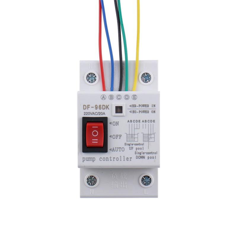
SenzaInterruttori modello
