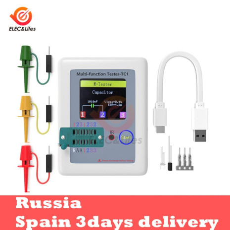
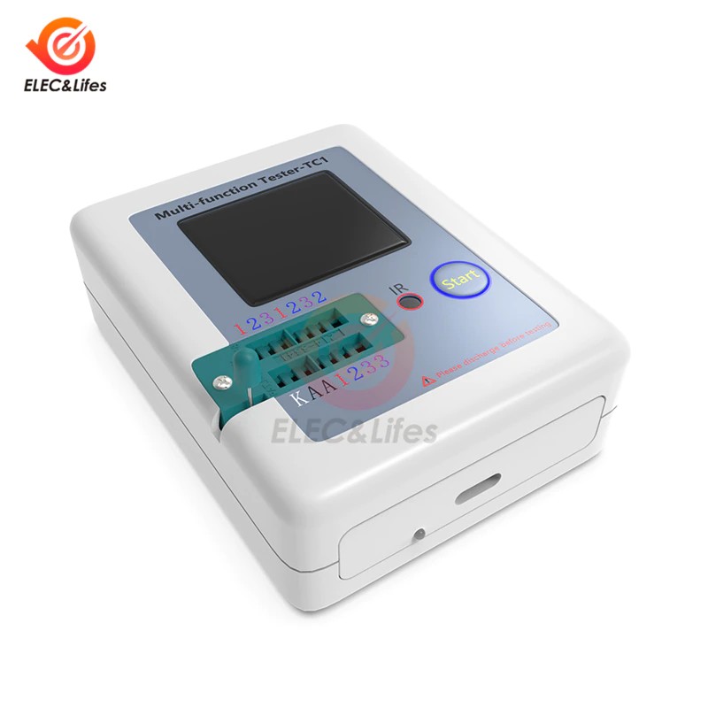
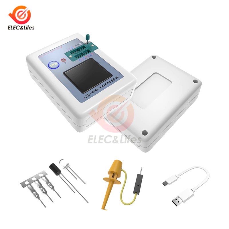
LCR-TC1 1.8 Polegada lcd backlight transistor tester com 160*128 tft display a cores de detecção gráfico do resistor do capacitor do triode do diodo
![]()
Características:
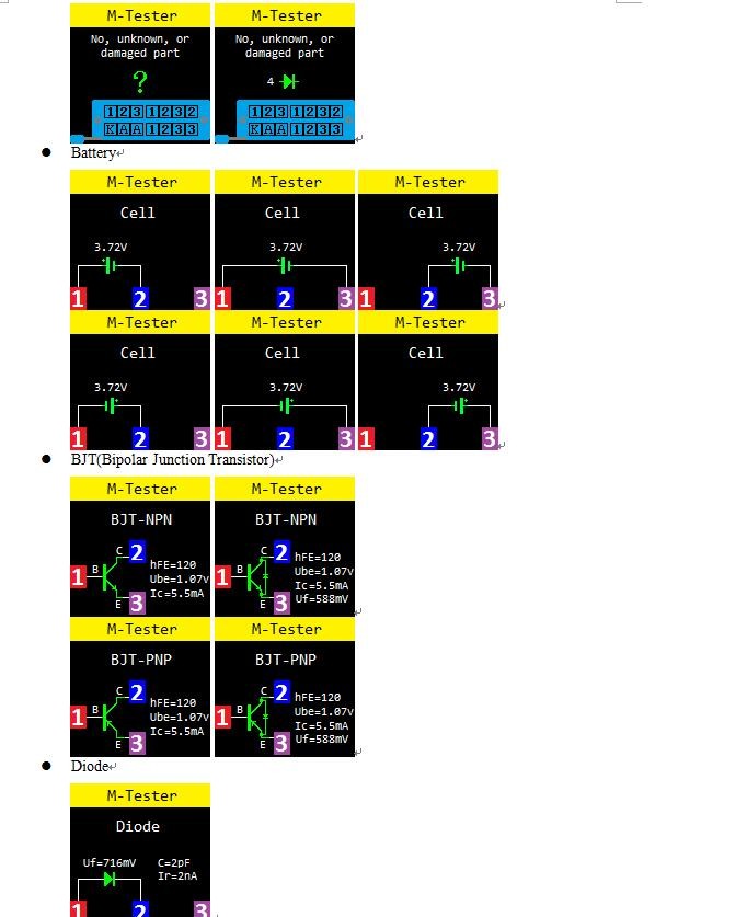
Pode ser amplamente utilizado para detectar npn e pnp transistor, capacitor, resistor, diodo, triode, n-canal e p-canal mosfet, igbt, jfet, triac e bateria etc.
Ele também pode ser usado para detectar formas de onda infravermelha.
Igualmente pode detectar o diodo de zener e tem a função da auto-calibração.
Após a detecção, alinhar o controle remoto infravermelho com a luz "ir", em seguida, pressione o botão no controle remoto, se o detector decodificar com sucesso, ele irá exibir o código de dados e forma de onda infravermelha.
Uma operação de botão, detectar automaticamente e desligamento, e você pode pressionar o botão multi-funcional para fechar o detector também.
Coloque os pinos do componente na área correspondente, em seguida, discar o pequeno punho e o detector irá testá-lo automaticamente, finalmente os resultados serão exibidos na tela tft backlight claramente.
Não como o habitual preto e branco display, este detector irá mostrar resultados em cores.
Destaque:
1.Transistor Tester
Detecção automática do diodo zener 0.01-30v
Teste do auto com calibração automática
2. decodificador RI
Codificação de apoio IR Hitachi
IR exibição da forma de onda
Infravermelho receber instrução
3. outras Características
Resultados de medição usando display gráfico tft (160x128)
Uma operação de tecla
Desligamento automático (timeout configurável)
Bateria recarregável do li-íon de alta capacidade incorporado
Detecção de tensão Da Bateria Li-ion
Apoio Chinês e Inglês
Especificações:
Display: 160*128 tft tela
Escala do diodo: < 4.5v
Diodo zener: transistor detectar área: 0.01-4.5v
Diodo zener detectar área: 0.01-30v
Escala triac: igt <6ma
Capacitância: 25pF-100mF
Resistor: 0.01-50mΩ
Indutância: 0.01mh-20h
Bateria: 0.1-4.5v
Modo de energia: bateria de lítio recarregável (incluída)
Tamanho do artigo: 8.8x8x2.8cm / 3.47x3.15 x 1.10in
Peso do artigo: 111.5g / 3.94oz
Instruções de operação:
1. multi-função chave tem duas ações:
Imprensa curta: pressione a tecla e não menos de 10 ms, tecla de liberação dentro de 1.5 segundos
Imprensa longa: pressione a tecla mais de 1.5 segundos
2. ligar:
No estado de desligamento de energia, pressione rapidamente a tecla multifunções, o testador é ligado e medido automaticamente.
3. power on & interface de medição:
![]()
4. detectar transistor:
No estado de desligamento de energia ou o teste é concluído, coloque o elemento de teste na área de teste do transistor do assento de teste, e pressione o punho de bloqueio, pressione curto a tecla multifunções, o testador mede automaticamente, exibição gráfica dos resultados da medida quando o teste está completo.
Aviso: certifique-se sempre de descarregar capacitores antes de conectá-los ao testador! O testador pode ser danificado antes de você ligá-lo!
Aviso: não recomendamos usar o testador para medir a bateria! A tensão da bateria deve ser inferior a 4.5v, caso contrário o testador pode ser danificado!
Parâmetros de desempenho:
O verificador multifunction pode identificar automaticamente elementos e detecção automática de layout do pino, e faixa de comutação automática.
Os principais parâmetros de desempenho são os seguintes:
Componente | Gama | Descrição Do parâmetro |
BJT | - | Hfe (ganho de corrente cc), ube (tensão do emissor de base), ic (corrente do coletor), iceo (corrente de corte do coletor (ib = 0)), ciem (coletor de corrente curta), uf (tensão para a frente do diodo de proteção) ③ |
Diodo | Tensão para a frente <4.50v | Tensão para a frente, capacitância do diodo, ir (corrente reversa) ② |
Diodos duplas | Tensão para a frente |
Diodo Zener | 0.01-4.50V (Área de teste do transistor) | Tensão para a frente, tensão reversa |
0.01-20V (Área de teste de diodo zener) | Tensão reversa |
MOSFET | JFET | Cg (capacitância da porta), id (corrente de drenagem) em vgs (portão para voltag do limiar da fonte), uf (tensão dianteira do diodo de proteção) ④ |
IGBT | Id (corrente de drenagem) em vgs (portão para voltag limiar da fonte), uf (tensão para a frente do diodo de proteção) ④ |
MOSFET | Vt (portão ao voltag do limiar da fonte), cg (capacitância da porta), rds (dreno à fonte na resistência), uf (tensão dianteira do diodo de proteção) ④ |
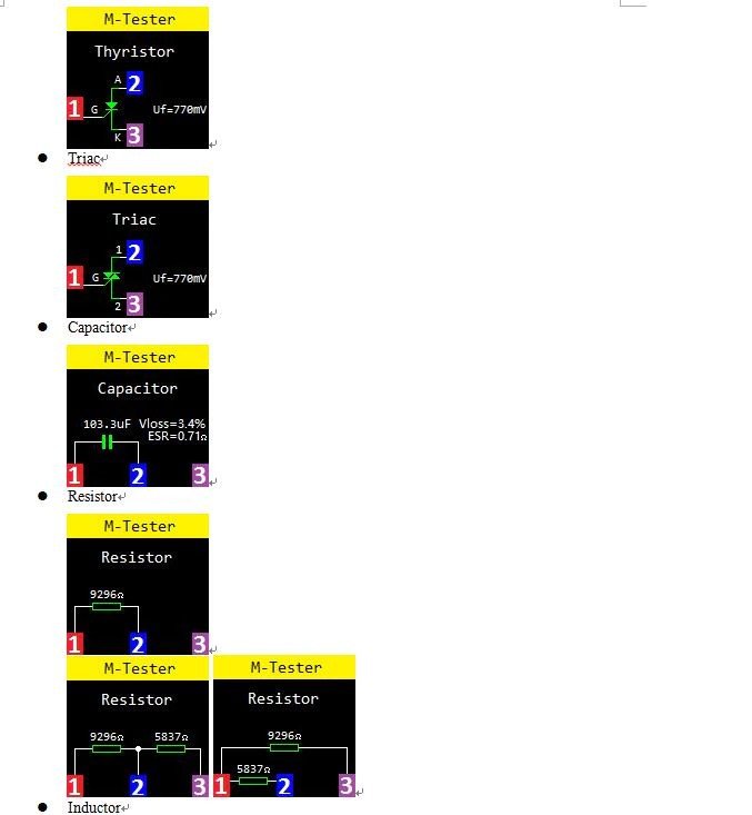
Thyristor | Igt (corrente do disparador da porta) <6ma | Gate trigger tensão |
Triac |
Capacitor | 25pF-100mF | Capacidade, esr (resistência equivalente da série), vloss ① |
Resistor | 0.01-50MΩ | Resistência |
Indutor | 0.01mh-20h | Indutância, resistência dc ⑤ |
Bateria | 0.1-4.5V | Tensão, a Polaridade Da Bateria |
Nota ①: iceo, ices, uf exibidos somente quando efetivo
Nota: capacitância do diodo, ir (corrente reversa) exibido somente quando eficaz
Nota: exibido somente quando tem diodo de proteção
Nota: esr, vloss exibido somente quando eficaz
Nota: medição de indutores com resistência abaixo de 2100Ω
FAQ
Pergunta | Causar | Solução |
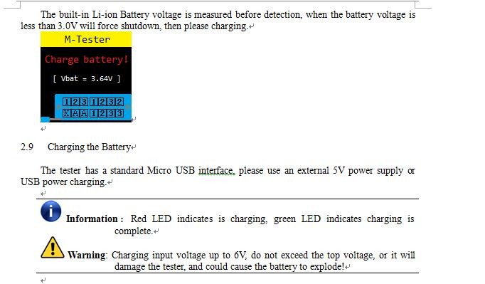
Não pode ligar | Built-in bateria li-ion está morto | Carregar a bateria do li-íon, métodos de carregamento veja a seção 2.9 |
Medições imprecisas | Parâmetros de calibração impreciso | Por favor, re-calibração, ver seção 2.4 |
| | |
NOTA:
1. built-in bateria do li-íon, é estritamente proibido o verificador imerso na água, ou perto de uma fonte de calor!
2. para sua segurança pessoal, por favor cumprir rigorosamente com o uso de especificações e precauções da bateria de li-ion!
![]()
![]()
![]()
![]()
![]()
![]()
![]()
![]()
![]()
![]()


